July 18, 2005
By Graeme Nattress
If there’s one topic more than any other in video production, especially in North America, that causes confusion, misinformation and probably more posts to more message boards than any other, it’s black levels in digital video.
In this article I will explain where the issues are with black levels in digital video, with specific regard to how Final Cut Pro handles and displays them. I’ll also look at how Final Cut Pro handles black and white levels in general, and what it does when importing or exporting still frames or images. Final Cut Pro has settings for “White” and “Super White” in the timeline and I’ll explain how they effect video and still image import / export.
One of the most annoying things about the technical aspects of video production is that everything changes when you cross international borders. Analogue video levels differ the world over, but fortunately, digital video levels are standard across the world. North America, in particular, differs from the rest of the world in how it handles black levels in analogue video, and it is this difference, the infamous 7.5 IRE setup that causes more confusion than anything else.
Due to the technical nature of this article, I’ve summarized the key points at the end of each section. If you remember these key points, you won't go far wrong!
Measuring Video Levels We’re going to look at how Final Cut Pro, digital video (in general, not just miniDV) and analogue video represent our video image. The three components of video are made up from luma , and two chroma components (see: Chroma Sampling: An Investigation for more information). In this article, we will only concern ourselves with luma, which represents the lightness of the pixels of the video image and the analogue and digital levels which are are used to store or represent it. Analogue VideoIn analogue video, all levels are represented by voltages, and measured in IRE or “Institute of Radio Engineers” units. In North America, the range of values for video luma levels is from 7.5 IRE (darkest black reference level) to 100 IRE (brightest white reference level). The rest of the world uses a 0 IRE to 100 IRE range. Japan, being an NTSC country, originally used the 7.5 IRE standard for black, but changed to the 0 IRE for black standard around 1985. The reason behind the use of 7.5 IRE “setup” (7.5% Setup, as it is often referred to as) was to help early television receivers to differentiate between black in the video image and video blanking, the periods in which the beam that scans the image in a CRT monitor has to move to the start of a new line, or the start of a new field after the previous one has been drawn. There is no current technological need for 7.5 IRE setup to help modern receivers, and indeed, it is a hinderance to maintaining black level calibration, but it is still used in North America for historical compatibility reasons.
An example of a software switch to set 0 IRE or 7.5 IRE Setup, in this case, from the control panel of a Decklink HD Pro.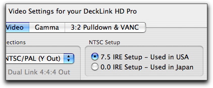
Setting 7.5 IRE Seup in the Decklink Control Panel
Digital Video
In digital video, all levels are represented by the binary language of computers, but for our ease, we shall use decimal equivalents. Instead of the continuously variable voltage of analogue video, digital video uses a set of discrete values to represent the video levels. Each allowable video level in this system can be given a code number. In an 8bit system there are 256 (2 to the power of 8) allowable codes, numbered from 0 through to 255. Most modern digital systems use 8bit encoding (or quantization), but some high end systems use 10bits or more. For simplicity, we’ll only be discussing 8bit video here.
In the ITU-R BT.601-4 specification, reference black is at code 16 and reference white is at code 235. Codes 0 and 255 are “reserved” and not used for video encoding. Codes 1 though 15 are for “super black” and codes 236 through 254 are for “super white”. The super black and super white codes are footroom and headroom for the accurate preservation of transient peak excursions beyond the legal video range. It should be noted that many digital video cameras routinely generate super white (above white, or above code 235) video levels and these need to be dealt with before such video can be safely broadcast.
Final Cut ProIt is often hard to get Final Cut Pro to tell us exactly what our video looks like, and you will often hear, when people complain that their video just doesn’t look right inside Final Cut Pro, “Did you check it on your NTSC or PAL monitor?” Final Cut Pro has a hard job when we ask it to display video on the computer monitor because the computer monitor is very different to a video monitor (PAL or NTSC) in many ways. Computer monitors often have a different “gamma” (gamma is the name given to the non-linearity in the values that represent the video image) to video monitors, and they handle video levels differently. Therefore, the primary tool inside Final Cut Pro for monitoring video levels is the Waveform Monitor. The waveform monitor shows us all the levels in the video on a vertical axis, with dark levels at the bottom and bright levels at the top.
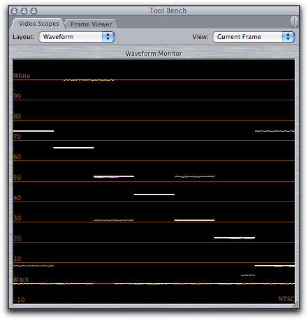
Final Cut Pro’s Waveform monitor, with 0% to 100% scale
The Waveform Monitor in Final Cut Pro uses unnamed units of measurement in a percentage scale, so we’ll call them FCP units. You can see that Final Cut Pro puts the words “black” and “white” on it’s measuring scale that ranges from -9%FCP to 109%FCP. Black is placed at 0% and white is placed at 100%. Remember these are FCP units and not IRE. As Final Cut Pro only deals with video as digital video, there is a direct relationship between digital codes and %FCP. Although the scale in Final Cut Pro goes down to -9%FCP, this would lead to a negative digital code. I am therefore not certain of the actual minimum %FCP, but a value of -7% would lead nicely to the lowest possible digital code of 1.
|
8bit Digital Code |
%FCP |
Name |
|---|---|---|
|
? |
-9 |
|
|
16 |
0 |
Black |
|
235 |
100 |
White |
|
254 |
109 |
It is very important that you keep your black levels inside Final Cut Pro at the 0%FCP mark (other than for creating a special video effect) as all the video effects that you can use in Final Cut Pro expect black to be at 0%FCP and may not work correctly or produce the desired result if they are at a raised value.
Digital Video Levels and IREBecause IRE refers only to analogue video, and digital codes and %FCP only refer to digital video, we only have to concern ourselves with conversions between them at the points in any video editing system where analogue video is converted to digital, or digital video is converted to analogue. At these points of conversion, it is important to understand what is happening to the video so that you can determine if your video is in the correct limits of video levels for broadcast. There are many different ways to get video into and out of a Final Cut Pro editing system, from video cameras, DV converters, decks, add on PCI cards, add on Firewire devices etc. In each, there will be a device that converts digital to analogue (a D to A converter) and analogue to digital (A to D converter). It is the job of these devices to accurately map analogue voltages to and from the correct digital codes.
Digital To Analogue Converter |
Addition of 7.5 IRE in the Analogue signal |
||
Analogue to Digital Converter |
Removal of 7.5 IRE in the Analogue signal |
||
Digital Input (Firewire / SDI etc.) |
Addition of setup in the digital signal by adding 16 to the value for black |
||
Digital Output (Firewire / SDI etc.) |
Analogue image from the imaging chips of the camera |
||
Analogue Input (composite, component, s-video) |
Digital Signal |
||
Analogue Output (composite, component, s-video) |
Analogue Signal |
Key to diagrams
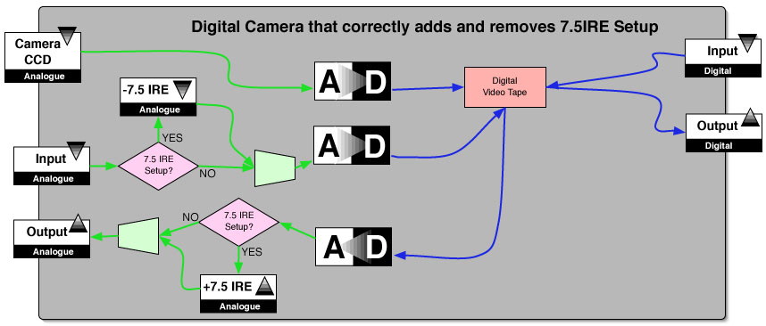
Correct Addition and Removal of 7.5 IRE Setup
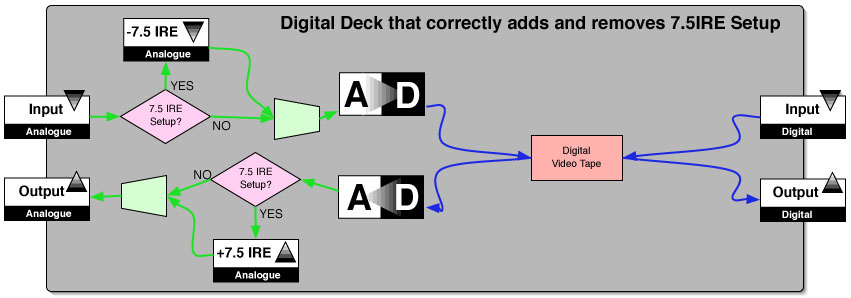
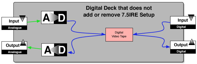
Above is a block diagram of a Digital Deck that will correctly add and remove 7.5 IRE Setup. The Digital Deck in the diagram could be a Digital Betacam deck, a DVCpro50 Deck or a high end DVCAM deck (there are very few low end decks, mainly some from JVC, that correctly add and remove 7.5 IRE Setup). The deck's add / remove 7.5 IRE Setup switch is shown in the diagram by the purple diamond. Setting the switch to "YES", you can follow the route the signal takes as 7.5 IRE Setup is added or removed. With the switch in the "NO" position, the addition or removal of 7.5 IRE Setup is bypassed. The Analogue to Digital converter will be set to map 0 IRE to code 16, and 100 IRE to code 235. The removal of 7.5 IRE Setup is done (if necessary) ahead of the Analogue to Digital Converter. When you play back a digital tape, the Digital to Analogue converter correctly maps code 16 to 0 IRE and code 235 to 100 IRE, and if necessary, adds 7.5 IRE setup to the analogue signal after it has been converted from digital. It can therefore be seen how the digital inputs and outputs It will produce the results in the table and diagrams below:
|
Analogue 0 IRE Setup |
8bit Digital Code |
Analogue 7.5 IRE Setup |
|---|---|---|
|
0 IRE |
16 |
7.5 IRE |
|
100 IRE |
235 |
100 IRE |
If the signal in the Digital Deck is kept completely in the digital domain, you can also see that the signal goes nowhere near the analogue circuitry and does not have any 7.5 IRE Setup added or removed from the signal. Remember, 7.5 IRE Setup is a purely analogue phenomena, and is only ever relevant for North American NTSC. Setup should only ever be removed or added to an analogue signal - never a digital one.
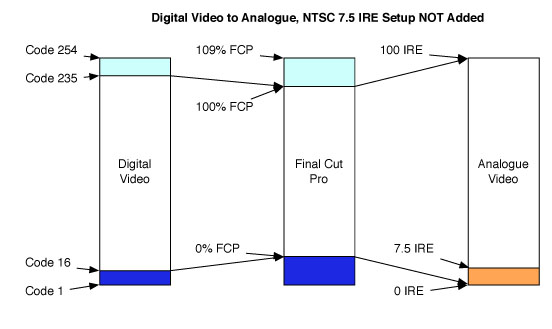
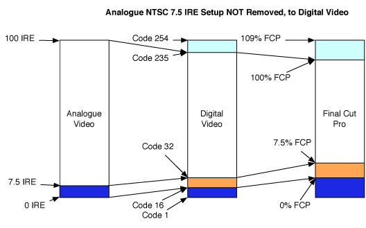
These diagrams show what happens to video levels in the deck that will correctly add and remove 7.5 IRE Setup.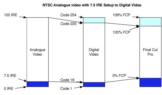
The left hand bar represents the range of values in NTSC Analogue Video. The key values are marked 0 IRE, 7.5 IRE and 100 IRE. The blue block at the bottom represents the "super black" region. The arrowed lines from the first bar to the second show how the key values get mapped from the analogue world to the digital world. The cyan block at the top represents the "super white" region.
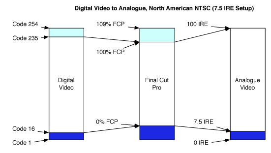
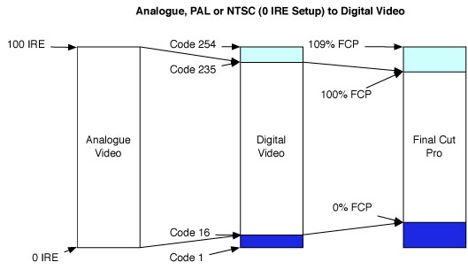
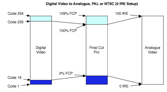
In all the above cases, the levels are mapped to the correct values.
One important thing to remember, is that the digital codes are a world standard no matter whether you’re using a 0 IRE Setup or 7.5 IRE Setup analogue video system. Often the video input / output device will have a switch (maybe a software switch in the devices drivers, a physical switch on the unit itself, or in it’s menu system) that will determine the standard it will accept on it’s analogue inputs or deliver on it’s analogue outputs. Because some devices do not have such switches, or have such switches but they work incorrectly we have to be incredibly careful.
PAL users are lucky as they never have to deal with issues of 7.5 IRE Setup (until they move from a PAL country to a NTSC country, and have to learn the new system). North American NTSC users who have grown up with 7.5 IRE Setup “know” that blacks must “always” be at 7.5 IRE and will set ALL devices to 7.5 IRE with sometimes disastrous consequences because not all digital video devices deal with 7.5 IRE Setup correctly.
Not Adding or Removing 7.5 IRE Setup
This next diagram could equally be the block diagram of a PAL Digital Video deck (which does not require the addition or removal of 7.5 IRE Setup), a Japanese NTSC deck (Japanese NTSC, as noted above, does not now use 7.5 IRE Setup) or, more importantly, a North American NTSC deck that does not deal correctly with the addition or removal of 7.5 IRE Setup on it’s analogue inputs or outputs.
Many affordable digital video decks (Sony DSR-11, DSR-25 etc.) and especially digital video cameras (mostly miniDV and DVCAM) do not deal with 7.5 IRE Setup correctly. I do not fully understand the reasons for this failing, but it probably has something to do with most video cameras originating from Japan where they use 0 IRE Setup and efforts to keep the cost of these devices as low as possible.
Let me illustrate with another table and diagrams what happens in these devices:
|
Analogue Input |
8bit Digital Code |
Analogue Output |
|---|---|---|
|
0 IRE |
16 |
0 IRE |
|
7.5 IRE |
32 |
7.5 IRE |
|
100 IRE |
235 |
100 IRE |
When the Deck is PAL, or when a NTSC deck is used with Japanese Analogue NTSC, the results are correct:


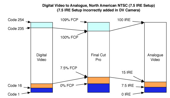
But when such a NTSC deck is used with North American analogue NTSC, the results are wrong:

In the above diagram, the orange block represents an incorrect black level. Because the deck expected analogue NTSC black at 0 IRE not 7.5 IRE, the 7.5 IRE black gets mapped to the incorrect value of code 32, which Final Cut Pro represents as 7.5 % FCP.
Similarly, in the above digram, the orange block represents how the correct black level in Final Cut Pro of 0% FCP gets mapped to the incorrect (for NTSC) black level of 0 IRE because the deck does not know how to add 7.5 IRE setup.
You can see that when a North American NTSC analogue video is dubbed to digital with, say, a DSR-11, the 7.5 IRE Setup is not correctly removed before conversion to digital. In the block diagram above, you can see that, comparing to the digital deck that correctly adds and removes 7.5 IRE Setup it lacks the circuitry to do so. Because the deck is expecting analogue black to be at 0 IRE, and it receives it at 7.5 IRE instead, digital black now appears at code 32, which is approximately 7.5%FCP. It is confusing that black ends up at 7.5%FCP because to someone brought up with North American NTSC, that figure would look totally correct to them, but as we now know, it is actually wrong. Black should always be at 0%FCP, because that is code 16 digital, which is correct to ITU-R BT.601-4 specifications.
NTSC Camera that Correctly Adds 7.5 IRE Setup
Below is a block diagram of a NTSC digital video camera that correctly adds 7.5 IRE Setup. It’s important to note that in this camera, the 7.5 IRE Setup is added after the digital video has been converted to analogue. The digital signal that gets recorded to tape is in no way effected by the addition or removal of 7.5 IRE Setup because Setup is a purely analogue phenomena. This camera will always produce a digital video tape with black levels at the correct
ITU-R BT.601-4 specifications of code 16.
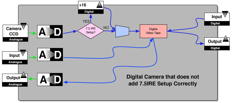
NTSC Camera that adds 7.5 IRE Setup Incorrectly
Below is a block diagram of a NTSC digital video camera that does not add 7.5 IRE Setup correctly. For example the Sony PD-150, PD-170, Canon XL1 and most other consumer and prosumer DV cameras could be represented by this diagram. You can see that in the digital camera represented by this diagram, 7.5 IRE Setup is produced on the analogue outputs by adding 16 to the digital code before the digital signal gets recorded to tape. Although this method will produce black at 7.5 IRE on the analogue outputs, it has done so in a way that records incorrect digital levels to tape, thus lowering quality and producing an incompatible digital video tape that does not meet ITU-R BT.601-4 specifications. In addition, any analogue video dubbed to digital using the analogue inputs on the camera will not have 7.5 IRE Setup correctly removed, again producing a digital tape with non-standard black levels.
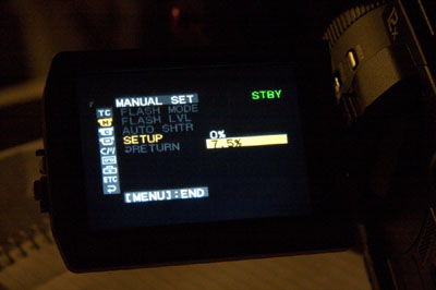
This image shows the "SETUP" menu on a Sony PDX-10. The menu gives you the choice of "0%" or "7.5%" . The Sony PDX10 adds setup incorrectly and will record the 7.5 IRE Setup in the digital signal to fake the addition of 7.5 IRE Setup on the analogue outputs.
As you can see, in these devices, 7.5 IRE, which in a video system with 7.5 IRE Setup represents reference black, gets recorded as digital code 32, which as we know from how digital video is encoded and the ITU-R BT.601-4 standard, is the incorrect value. The correct value is always code 16. Similarly, digital video, which has the correct levels in both the digital video tape, and in Final Cut Pro, will produce incorrect levels for North American NTSC if this camera is used as a Digital to Analogue converter to make, say, a VHS or BetacamSP dub of your DV edit.
Worse still is what happens when such a digital video tape (either produced incorrectly from a analogue to digital dub, or because of incorrect levels set inside Final Cut Pro, or from a digital video camera which does not add 7.5 IRE Setup correctly) with incorrectly recorded black levels is played back on a deck that deals with 7.5 IRE Setup correctly.
This can easily happen if you shoot on, say a PD-150 and have “Setup” switched on, edit in Final Cut Pro and leave the black levels at 7.5%FCP, output the edited programme back to DV tape, and deliver that tape to your local North American broadcaster. Your local broadcaster, if they accept a master on DVCAM will no doubt either injest digitally (into a playout system that will be to ITU-R BT.601-4 specifications and expect black at code 16) or via analogue using a DVCAM deck that correctly adds 7.5 IRE . If they broadcast from a digital server, 7.5 IRE setup will be added as part of the final Digital to Analogue conversion, and because we have given them a digital tape with Setup added in the digital domain, Setup will have been added twice, and our blacks will now be at 15IRE and look milky. Similarly, if they broadcast from the analogue copy they made using their pro DVCAM deck, Setup will also have been added twice, and blacks will again be at 15IRE and look milky. It is very important to avoid either of these situations by making sure your digital black levels are correctly placed at code 16 which is represented by 0%FCP in Final Cut Pro’s scopes.
This table and following diagrams illustrate what can happen when blacks are incorrectly recorded at code 32.
| 8bit Digital Code |
Analogue Output 7.5 IRE Setup |
|---|---|
16 |
7.5 IRE |
32 |
15 IRE |
235 |
100 IRE |
In this case, because the deck is correctly interpreting digital code 16 as black, and it knows that black should be at 7.5 IRE, it really gets the black at digital code 32 wrong, and places it at 15IRE which will make your blacks look milky, and probably cause a costly failure at your programme’s quality control tech review.
Reduced Dynamic Range
Recording black at code 32 rather than the correct code of 16 will also lead to reduced dynamic range in the recorded video image. This is especially important to avoid in a video camera, as what is not recorded to tape (in terms of dynamic range) can never be put back in at a later date. Most affordable digital video cameras have a switch (usually hidden in a sub menu) to add 7.5 IRE Setup. As illustrated above, these cameras do not deal with Setup correctly and will record reference black at code 32.
When 8bit digital video is recorded correctly, with black at code 16 and white at code 235, there are therefore 219 different levels that are available to represent all the tones in the image you are recording, and this is just enough to do so without leading to visible banding artifacts in the image. If black is instead recorded incorrectly at code 32, there are only 203 levels left to record your image. Another way to look at this is the equivalence between decreased dynamic range and increased levels of noise. Either way, it’s not something we want in the video being recorded by our camera. Also, it should not be forgotten that if video is recorded with black at code 32, we will (or should) fix it inside Final Cut Pro, which may lead to increased render times for the project, and a decrease in quality due to the rounding errors inherent in mapping the code 32 to code 235 range back to the correct code 16 to code 235 range.
Typical Problems Dealing with 7.5 IRE Setup
For these problems, I am assuming you are working with North American NTSC which requires Setup to be at 7.5 IRE.
Accurate Video Monitoring
To ensure accurate video monitoring, your video monitor should be correctly calibrated to your system. The key thing to remember is that the “Brightness” control on your monitor should more correctly be labeled “Black Level”. The setting of the black level control on your monitor will determine which analogue voltage you the viewer will perceive as black when you view the image on the monitor. By adjusting this control correctly you can calibrate your monitor to show you a true image whether your DV deck, for instance, adds 7.5 IRE setup correctly or not to it’s analogue outputs.
Problems can occur when you monitor multiple video sources through the same monitor, for instance an analogue deck and a digital deck. In this situation, if the digital deck does not correctly add 7.5 IRE setup, you would need two different monitor calibrations, which is tricky to achieve. The solution is to add a “proc amp”, an analogue video manipulation device that can raise the analogue output from the digital deck by 7.5 IRE, making up for the lack of such circuitry inside the deck itself.
Dubbing from Digital to Analogue Tape
If your digital tape deck does not correctly add 7.5 IRE Setup, you should add a proc amp to the analogue outputs of your DV deck, with the proc amp set to add 7.5 IRE Setup.
If you do not have a proc amp, another solution is to make a DVD of your project, and because most DVD players in North America correctly add 7.5 IRE Setup to their analogue outputs, you can then dub from your DVD to your analogue tape.
Dubbing from Analogue to Digital TapeIf your digital tape deck does not correctly remove 7.5 IRE Setup, you should add a proc amp to the analogue inputs of your DV deck, with the proc amp set to remove 7.5 IRE Setup. Determining if your digital video camera adds 7.5 IRE Setup correctly or not
An easy way to determin if your video camera correctly adds 7.5 IRE Setup is to perform a simple experiment. All it takes is for you to put the lens cap on the camera and record a few seconds of black with the "Add setup" switch or menu on, and a few second with it set to off. Capture your digital video into Final Cut Pro, and examine the video in the waveform monitor. You should see a horizontal line at 0% FCP, which is where black is meant to be in digital video. If the "on" and "off" sections of video both have black at 0% FCP then your camera must be only adding 7.5 IRE Setup on the analogue outputs, and is therefore adding 7.5 IRE Setup correctly. If, however, the "on" section of the video shows a raised black level of about 7.5% FCP, then the camera is adding setup digitally, and is therefore adding it incorrectly. Things To Remember
- Digital video does not have 7.5 IRE Setup. This applies to ALL digital formats, from DV and DVD to Digital Betacam, DVCpro50 and all HD formats.
- Digital video levels are not measured in IRE.
- Digital levels are the same the world over, specified by ITU-R BT.610-4 - code 16 is black, code 235 is white. Although High Definition formats conform to their own standards, they still use exactly the same range of values for encoding luma levels, code 16 being black and code 235 being white.
- Final Cut Pro represents the 16 to 235 range as 0% to 100% in it’s waveform monitor.
- Be very careful before setting a digital video camera to add 7.5 IRE Setup as most likely it will not do it correctly and create a digital video tape with black values out of specification and use a reduced dynamic range to record the picture.
- When dubbing an analogue source to a digital one, be sure to set the digital deck to correctly remove 7.5 IRE Setup if necessary.
- When dubbing a digital source to an analogue one, be sure to set the digital deck to correctly add 7.5 IRE Setup if necessary.
- Do not set blacks in FCP to 7.5%. Blacks in FCP should always be at 0%.
- Do not raise your blacks in FCP to 7.5% to compensate for a deck or camera that does not correctly add setup because doing so will reduce image quality - use a proc amp instead.
- If you get a facilities house to do a North American NTSC BetacamSP (or other analogue format) dub to DV or DVCAM for you, scrutinize it carefully to ensure that the black levels appear at 0% FCP in Final Cut Pro’s waveform monitor.
- If you are capturing video with a card like a Decklink or an external device such as an AJA IO, then be sure to set it to correctly add or remove 7.5 IRE setup as necessary.
When you import a still image, a jpeg, a tiff etc. into Final Cut Pro, you have to be aware of how Final Cut Pro will convert your image from a computer based RGB space with black at 0,0,0 and white at 255,255,255 to the digital video space which has black at code 16 and white at code 235.
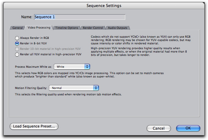
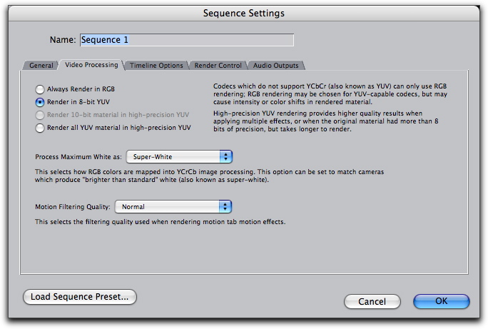
The import is dependent on a timeline setting in Final Cut Pro, called “Process Maximum White as”, and this decides how RGB colours are mapped into the Y’CbCr space.
|
White |
Super-White |
|||
|---|---|---|---|---|
|
8bit RGB Level |
8Bit Digital Code |
%FCP |
8Bit Digital Code |
%FCP |
|
0 |
16 |
0% |
16 |
0% |
|
255 |
235 |
100% |
254 |
109% |
It is therefore important not to pre-process the black and white levels of images before importing into Final Cut Pro, by, for instance, using “levels” in Photoshop to set black at 16 and white at 235, to take account of the differences between RGB and Y’CbCr because Final Cut Pro does it for you, and gives you no option, other than how to process maximum white.
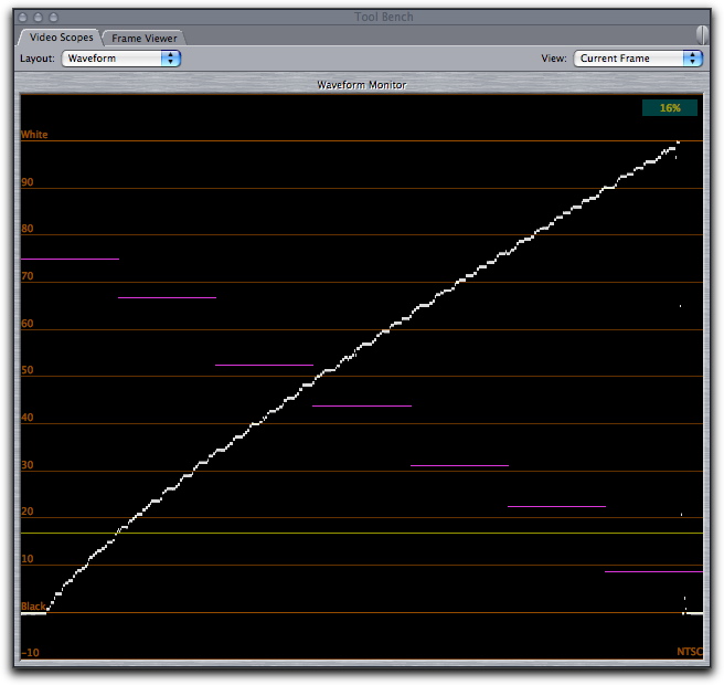
The following test image of a greyscale gradient from black through to white was used to produce the following results.

Final Cut Pro's waveform monitor was used to help us determine exactly what is happening.
Greyscale image, on “Super White” timeline
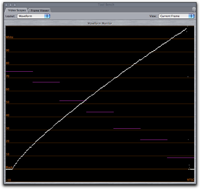

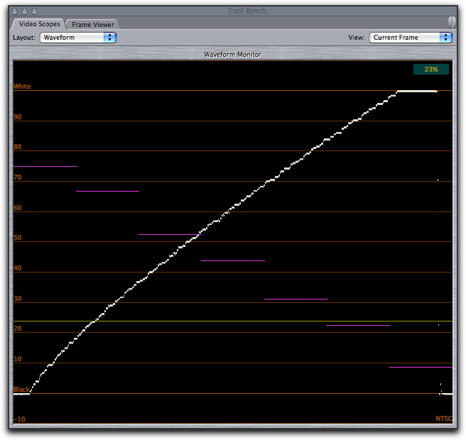
Greyscale image, on “White” timeline
In addition to the mapping of values, a slight gamma correction is also added of approximately 0.8. This can be easily seen in the waveform monitor images above. If the gamma had been 1.00, the line would be perfectly straight. This can be corrected inside Final Cut Pro, if desired, by applying a gamma correction of approximately 1.2, or by applying a gamma adjustment of about 0.8 in Photoshop before importing (Gamma numbers in Photoshop seem to be the reciprocal of gamma numbers in Final Cut Pro). Due to the lack of precision in Final Cut Pro’s look-up-table calculations, you will probably achieve smoother looking results by adjusting the gamma in Photoshop before bringing the image into Final Cut Pro. Remember always to keep an “uncorrected” master copy of your image as repeated image processing can degrade picture integrity.
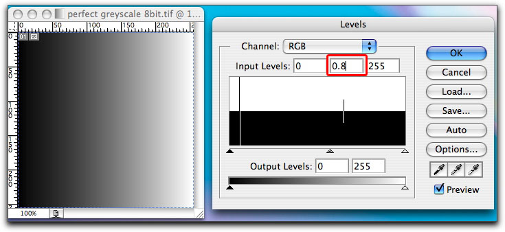
Adjusting Gamma in Photoshop “Levels” to compensate for Final Cut Pro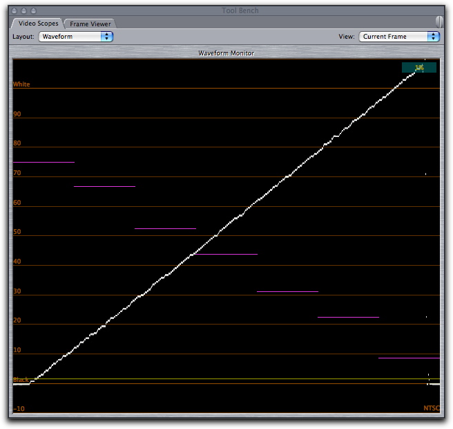
Waveform after Photoshop 0.8 Gamma Correction
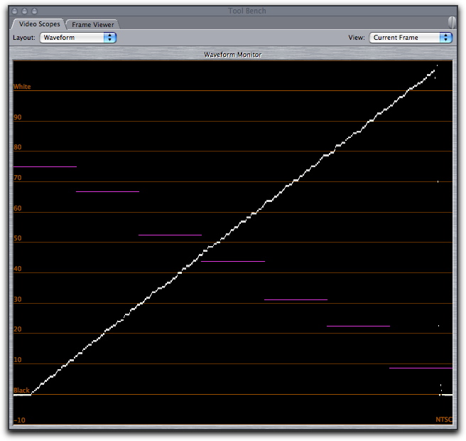
Waveform after Final Cut Pro 1.2 Gamma Correction
The “Process Maximum White as” setting does not effect video renders or video footage.
Exporting Stills From Final Cut ProUpon export, Final Cut Pro will ignore any super-black or super-white information in the video image and directly map the code 16 to code 235 (0% FCP to 100% FCP) range to the 0 to 255 computer RGB range. That means that if your image, whether from video or a still, has picture information above 100% FCP then that picture information will be lost on export.
Below is the waveform of an image imported into a “White” timeline, exported, and then re-imported into a “White” timeline.
Below is the waveform of an image imported into a “Super White” timeline, exported, and then re-imported into a “White” timeline. Notice how picture information has been “cropped” off the brightest part of the image and lost. This is because on export, Final Cut Pro maps the 0% FCP to 100% FCP range to the 0 to 255 RGB range, ignoring any picture information above 100% FCP and below 0% FCP.
White and Super White
Final Cut Pro has not always allowed you to choose "white" and "super white" as preferences. It is important to remember that this setting in Final Cut Pro only effects the import of still images.
The "white" and "super white" settings do not effect imported video in any way.
Most video cameras allow you to shoot and record a video image that will use video levels that go up into the "super white". Such "super white" video levels are not suitable for broadcast and need to be brought back down to the 100% FCP level in the waveform monitor, either through colour correction or use of the broadcast safe filter.
Final Cut Pro defaults the timeline setting to "white". If you import a still image with the "white" setting, it might look dull, but it will be within broadcast luma limits. You may still need to ensure it's chroma is within broadcast limits, but at least it's luma is correct.
If you are producing video for non-broadcast environments, you may wish to use all the video levels up to 110% FCP and set the timeline setting to "super white" to allow the imported images to use this full range.
Things To Remember
- Still images are RGB in a 0 to 255 range
- Levels above 100% FCP, 100 IRE or code 235 are called “super white”
- Final Cut Pro automatically converts images to fit into the 0% FCP to 100% FCP range when it is set to “White”.
-
Final Cut Pro automatically converts images to fit into the 0% FCP to 100% FCP range when it is set to “Super White”.
-
Final Cut Pro only
looks at the 0% FCP to 100% FCP range upon still image export, and maps this range to 0 to 255 RGB.
- Picture information can be lost on still image export if you have picture information in the 100% FCP to 110% FCP range.
- Final Cut Pro always applies a gamma correction of about 0.8 to imported still images. If necessary, this can be corrected by applying a gamma correction of 1.2 in Final Cut Pro or 0.8 in Photoshop.
- Don’t preempt Final Cut Pro’s conversion of still images by setting your blacks in Photoshop to 16 and whites to 235. Final Cut Pro expects you to use the full 0 to 255 RGB range.
- “White” and “super white” settings only effect the import of still images.
- “White” and “super white” settings do not effect video or video rendering.
Black and white video levels in video can be very confusing, especially if you’re moving from a traditional analogue workflow to a digital workflow. However, Final Cut Pro handles video levels correctly, and even names the black and white points in the waveform monitor to remind you where you black and white levels should lie.
It is important to remember that 7.5 IRE setup is a North American analogue NTSC issue and that it should be dealt with only whenever video moves from analogue to digital or digital to analogue. Dealing with it digitally can lead to problems, and a quality reduction in the video.
The world over, digital video levels are the same and defined by international standards.
Final Cut Pro gives the user very little choice in the handling of still images. Final Cut Pro also, annoyingly, adds a gamma correction to imported stills in an attempt to make up for the gamma differences between computer and video monitors. Worse still is the lack of official documentation on exactly what is happening, leaving us to perform experiments to determine the exact nature of what Final Cut Pro does.
As Final Cut Pro tries to move itself into more professional workflows, it is vital that Apple address these issues by allowing the expert user to fully define how RGB levels are mapped, and whether any gamma correction is added, and indeed, what the value of that gamma correction should be.
The diagrams in this article were produced with OmniGraffle an application that many of you will have received a free version of with their Macintosh. Omnigraffle is an excellent, flexible tool for producing diagrams, flowcharts, layouts and many kinds of graphics.
 |
Graeme Nattress is the software developer at Nattress Productions Inc. where he enjoys researching cutting edge algorithms for the improvement of video quality. He is a frequent contributor to the kenstone.net, LAFCPUG, 2-Pop and Creative Cow websites and forums. |  |